نمودار زیر نمای جلویی ماژول تاکومتر و نمای پشتی چندین ماژول ورودی/خروجی را نشان میدهد.
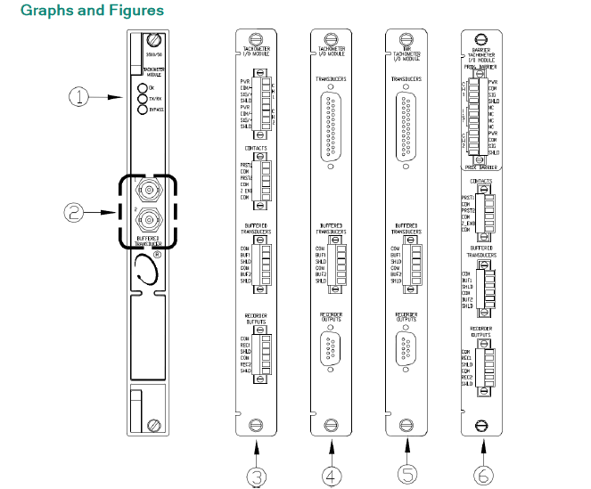
۱. چراغهای LED وضعیت--
۱۳۳۳۸۸-۰۲
۲. خروجیهای مبدل بافر شده
ماژول ورودی/خروجی ۳، ترمینالهای داخلی--
۱۳۳۴۴۲-۰۱
ماژول ورودی/خروجی ۴، ترمینالهای خارجی--۱۳۳۴۳۴-۰۱
۵. ماژول ورودی/خروجی، TMR، ترمینالهای خارجی--۱۳۳۴۵۰-۰۱
۶. ماژول ورودی/خروجی، مانع داخلی، ترمینالهای داخلی--۱۳۶۷۰۳-۰۱
۱۰. (یا: ۱۰.)
۳۵۰۰/۵۳
ماژول تشخیص سرعت غیرمجاز
سیستم تشخیص سرعت بیش از حد الکترونیکی سیستم بازرسی مکانیکی بنتلی نوادا سری 3500، یک سیستم تاکومتر افزونه با قابلیت اطمینان بالا و پاسخ سریع است که به طور خاص برای محافظت از سرعت بیش از حد ماشین آلات طراحی شده است. ماژول 3500/53 میتواند برای تشکیل یک سیستم رأیگیری 2 به 2 یا 3 به 2 (توصیه شده) استفاده شود. قاب 3500 برای نصب سیستم تشخیص سرعت بیش از حد نیاز به یک منبع تغذیه افزونه دارد.
هر ماژول تشخیص سرعت بیش از حد، سیگنالی از یک سنسور جریان گردابی یا سنسور مغناطیسی دریافت میکند که محدوده سیگنال ورودی آن از +10.0 ولت تا -24.0 ولت است. سیگنالهای خارج از این محدوده در داخل ماژول محدود میشوند. مناسب برای سنسور جریان گردابی Bentley Nevada 3300 8 میلیمتری، سنسور جریان گردابی دمای بالا (HTPS) 3300 16 میلیمتری، سنسورهای جریان گردابی 7200 5 میلیمتری، 8 میلیمتری، 11 میلیمتری و 14 میلیمتری، سنسور جریان گردابی 3300 RAM یا سنسور مغناطیسی.
معانی LED پنل جلویی (دیود ساطع کننده نور):
چراغ OK: نشان میدهد که ماژول ۳۵۰۰/۵۳ به طور عادی کار میکند.
چراغ TX/RX (ارسال/دریافت): نشان میدهد که ماژول 3500/53 در حال برقراری ارتباط با سایر ماژولهای درون فریم 3500 است.
چراغ بایپس: نشان میدهد که ماژول 3500/53 در حالت بایپس است.
چراغ LED حالت تست: نشان میدهد که ماژول 3500/53 در حالت تست است.
چراغ هشدار: نشان میدهد که وضعیت هشدار رخ داده و رله مربوطه فعال شده است. خروجی بافر سنسور: هر ماژول دارای یک کانکتور کواکسیال در جلو برای خروجی بافر است. هر کانکتور در برابر اتصال کوتاه و تخلیه الکترواستاتیک محافظت شده است. برای سرعت، سطوح هشدار (نقاط تنظیم) را میتوان پایینتر یا بالاتر تنظیم کرد. علاوه بر این، میتوان یک نقطه تنظیم خطر (سرعت بیش از حد) را برای سرعت تنظیم کرد. همه نقاط تنظیم هشدار توسط نرمافزار پیکربندی میشوند. نقاط هشدار قابل تنظیم هستند و معمولاً در محدوده مقیاس کامل 0 تا 100٪ قابل تنظیم هستند. تأخیر زمان هشدار: کمتر از 30 میلیثانیه در فرکانسهای بالاتر از 300 هرتز. برای سایر عملکردها، لطفاً به دفترچه راهنمای عملکرد و نگهداری سیستم حفاظت از سرعت بیش از حد 3500/53 مراجعه کنید.
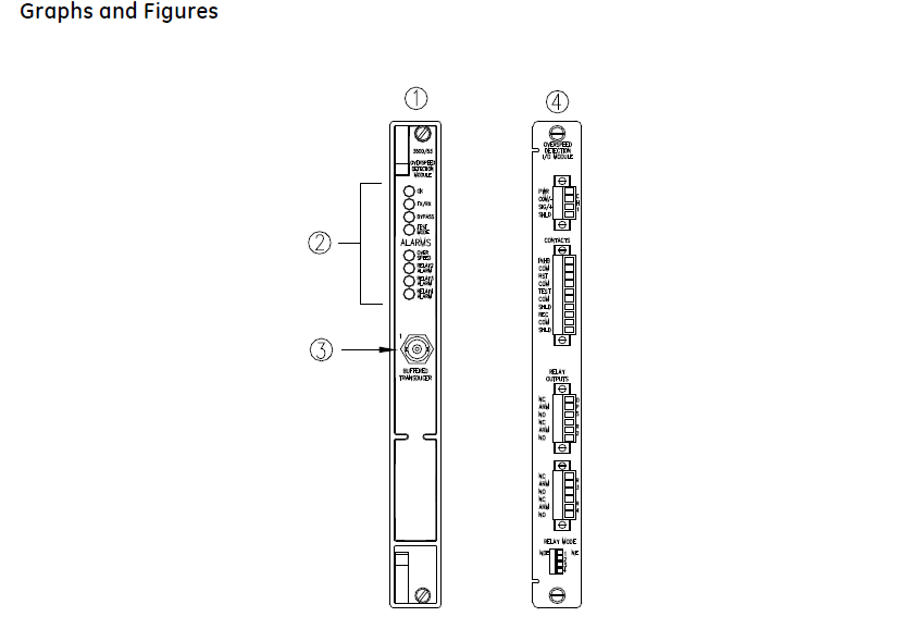
۱) ماژول اصلی، نمای جلو.--
۱۳۳۳۸۸-۰۱
۲) چراغهای LED وضعیت
۳) خروجی مبدل بافر شده. خروجی فیلتر نشدهای را برای مبدل فراهم میکند. خروجی در برابر اتصال کوتاه محافظت شده است.
۴) ماژول ورودی/خروجی، نمای عقب.--
۱۳۳۳۹۶-۰۱
۱۱. (یا: ۱۱.) ۳۵۰۰/۳۲ مگابایت ماژول رله ۴ کاناله
ماژول رله ۴ کاناله یک ماژول تمام قد است که چهار خروجی رله ارائه میدهد. هر تعداد ماژول رله ۴ کاناله را میتوان در هر یک از اسلاتهای سمت راست ماژول رابط داده گذرا قرار داد. هر خروجی ماژول رله ۴ کاناله را میتوان به طور مستقل برای انجام منطق رأیگیری برنامهریزی کرد.
هر رلهای که در ماژول رله ۴ کاناله استفاده میشود، شامل منطق درایو هشدار است.
برنامهریزی برای منطق درایو هشدار از منطق AND و OR استفاده میکند و میتواند از ورودیهای هشدار (وضعیتهای هشدار و خطر)، Not-OK یا PPL های جداگانه از هر کانال مانیتور یا هر ترکیبی از کانالهای مانیتور در رک استفاده کند. میتوانید این درایو هشدار را برای برآورده کردن نیازهای برنامه خود با استفاده از نرمافزار پیکربندی رک ۳۵۰۰ برنامهریزی کنید.
معانی LED پنل جلویی:
چراغ OK (دیود نورانی): وقتی ماژول به طور عادی کار میکند، چشمک میزند.
چراغ TX/RX: برای ارسال و دریافت استفاده میشود؛ وقتی ارتباط بین این ماژول و سایر ماژولهای موجود در فریم عادی باشد، چشمک میزند.
چراغ هشدار H: وقتی کانال رله در حالت هشدار قرار دارد، چشمک میزند.
نوع رله: دو رله تک پل دو حالته (SPDT) که به هم متصل شده و یک رله دو پل دو حالته (DPDT) تشکیل میدهند.
آببندی: رزین اپوکسی آببندی شده؛ عمر تماس ۱۰۰۰۰۰ سیکل در ۵ آمپر، ۲۴ ولت یا ۱۲۰ ولت.
حالت عملیاتی: هر کانال را میتوان با یک سوئیچ انتخاب کرد که در حالت عادی بدون انرژی یا در حالت عادی فعال باشد.
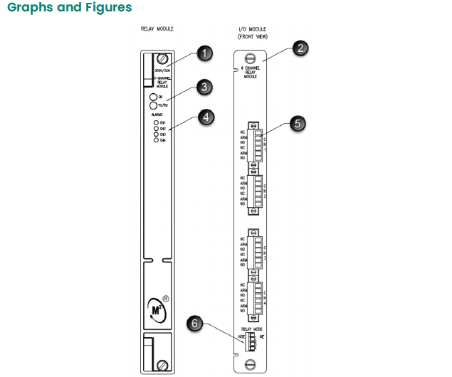
ماژول رله ۱.--
۱۴۹۹۸۶-۰۲
۲. ماژول ورودی/خروجی--
۱۲۵۷۲۰-۰۱
۳. چراغهای LED وضعیت
LED های کانال رله
۵. کنتاکتهای رله
۶. سوئیچ انتخاب حالت رله
نشانی : Unit 1904, No.96-2 Lujiang Road, Siming District, Xiamen
Phone/WhatsApp/Skype : +86 18060982349
پست الکترونیک : sales6@nseauto.com